
Wind design isn’t one section of the IRC — it’s a chain of connections running from the roof sheathing all the way down to the foundation, and the chain is only as strong as its weakest link. Here’s a breakdown of the core 2021 IRC provisions we design to for single-family wind resistance, with the applicable references. This applies to new construction in hurricane-prone regions (which, per the IRC’s own definition, includes all of Hawaii regardless of measured wind speed) — reach out to Dalkita for code consulting on your project.
R301.2, R301.2.1 – Every home has to be designed for the ultimate design wind speed (Vult) mapped for its site, using the current ASCE 7 wind speed maps referenced by the IRC. On most of our Kauai projects, that’s landing at Vult ≥ 130 mph — well into the range where the prescriptive toe-nail and standard fastening tables stop being sufficient and connector hardware, bracing length, and anchorage all get pushed up a tier. Wind loads on wall coverings, curtain walls, roof coverings, windows, skylights, and garage/exterior doors are pulled from Table R301.2(2), adjusted for building height and exposure per Table R301.2(3). Outside the prescriptive limits of the IRC’s wind provisions, R301.2.1.1 requires an engineered design under the Wood Frame Construction Manual (WFCM), ICC 600, ASCE 7, or the IBC.
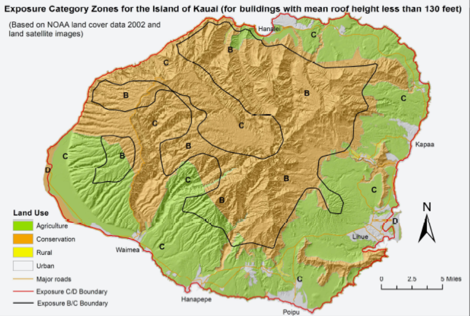
R301.2.1.4 – Before you can pull a single pressure off Table R301.2(2), you need an exposure category: B (urban/suburban/wooded), C (open terrain), or D (flat, unobstructed areas facing large bodies of water). Exposure category directly scales the design pressures on your walls and roof — a beachfront Exposure D lot and a sheltered Exposure B lot a mile inland can carry very different numbers even at the same 130 mph Vult.
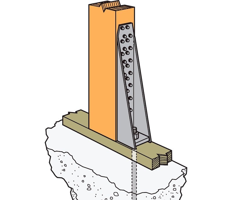
R301.1, R301.2.1 – The IRC requires a continuous load path: a documented, connected chain that transfers uplift and lateral wind loads from the roof assembly, through the walls, down to the foundation. This isn’t a single detail — it’s roof sheathing-to-framing, framing-to-top-plate, wall-to-wall (story to story), and wall-to-foundation, all sized to the same design pressures. A gap anywhere in that chain is where hurricane-force winds pull a roof or a wall off a house.
R802.11, Table R802.11 – Roof rafters or trusses have to be attached to their supporting walls with connectors sized for the calculated uplift force, which is a function of exposure category, roof pitch, and roof span. Standard toe-nailing per Table R602.3(1) is only permitted where the uplift force is 200 lbs or less, or under a narrow prescriptive exception (Exposure B, 90 mph, 5:12 pitch or steeper, 32-ft max span). At a 130 mph Vult, you’re almost always past that exception and into engineered connector hardware. A few common Simpson Strong-Tie connectors we spec along the load path:
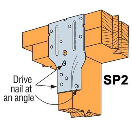
The connector’s rated capacity assumes every fastener hole is filled with the correct nail — a hurricane tie or stud-plate tie with half its holes empty is not providing the load path it was selected for. Given Kauai’s salt-air exposure, we also spec stainless-steel or ZMAX-coated hardware (e.g., SP2Z) at coastal and exposed sites rather than standard galvanized, since coastal corrosion can silently degrade connector capacity over time.
R602.10 – Braced wall lines resist lateral (racking) wind loads and are sized using braced wall panel methods (structural sheathing, let-in bracing, etc.) based on wind speed, exposure category, and story height. Required bracing length per braced wall line increases directly with design wind speed — this is often the section that most changes a wall schedule once you’re designing at 130 mph rather than a mainland-typical 90–110 mph.
R403.1.6 – Sill plates at exterior walls and braced wall lines must be anchored with minimum 1/2″ diameter anchor bolts, spaced a maximum of 6′-0″ on center, with a minimum of two bolts per plate section and one bolt located within 12″ (but not less than 7 bolt diameters) of each end of the plate. Bolts must embed a minimum of 7″ into concrete or masonry, with a nut and washer tightened on each. Plate washers are required over the full length of braced wall lines in higher seismic categories. This is the last link in the load path before the foundation — undersized or missing anchor bolts undo everything above them.
R301.2.1.2 – In windborne debris regions, exterior glazed openings (windows, glazed doors) must be protected from windborne debris — either with impact-rated glazing, an approved impact-resistant covering meeting ASTM E1996/E1886 (large or small missile test, depending on height above grade), or ANSI/DASMA 115 for garage doors. Because Hawaii is defined as a hurricane-prone region outright under the IRC, and windborne debris protection is triggered by Exposure D within one mile of a mean high-water line, this requirement reaches far more island sites than people expect — including many properties that don’t feel “coastal.” A code-recognized shortcut for the glazing itself: wood structural panels (plywood) at least 7/16″ thick and spanning no more than 8′-0″ are an accepted opening covering under this section, provided the panels are precut to fit, predrilled for anchorage, sized/fastened to resist the applicable component-and-cladding loads, and attached with permanent, corrosion-resistant hardware left in place on the building — not just plywood nailed up ahead of a storm with whatever’s on hand.
Code minimums aside, roof geometry itself is one of the biggest levers a designer has over how a house performs in a storm. FEMA and post-hurricane damage studies consistently show hip roofs outperform gable roofs in high-wind events: a gable roof presents a flat, vertical end wall that catches wind broadside and is prone to peeling or collapsing if not specifically braced, while a hip roof slopes on all four sides with no vertical end wall to catch a direct hit — wind loads resolve into the sloped planes instead. Lower, steeper roof pitches (within reason) also reduce uplift compared to shallow-pitch roofs. None of this is code-mandated, but on a 130 mph Vult site, choosing a hip form over a complex, multi-gable roof is one of the simplest design decisions that reduces both uplift forces and the number of vulnerable connection points before you even get to hardware selection.
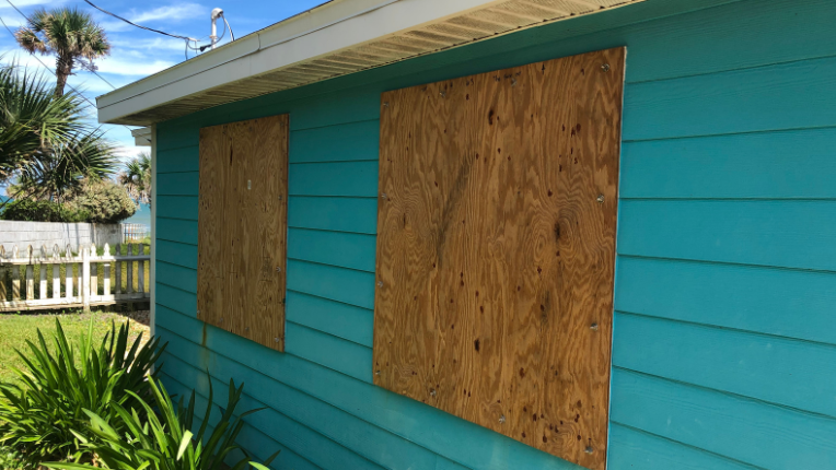
Table R301.2(2) – Roof coverings, siding, soffits, and trim aren’t part of the main wind-force-resisting system, but they still take direct wind pressure — and corner and edge zones see meaningfully higher negative (suction) pressures than the field of a wall or roof. This is why you’ll see tighter fastener schedules at gable ends, ridges, and building corners on a wind-rated project; Table R602.3(1) footnote provisions call out that tighter spacing explicitly.
None of these sections work in isolation — R301.2.1’s wind pressures only matter if R802.11’s connectors, R602.10’s bracing, and R403.1.6’s anchorage are all sized to match, and R301.2.1.2 closes the envelope so the whole system doesn’t fail from the inside out. Roof shape decisions made at the earliest design stage can reduce how hard that whole system has to work. Get in touch with Dalkita for code consulting on your next residential project.
Dalkita Architecture & Consulting is a licensed architecture firm serving residential and commercial clients across the US, with offices in Kaua’i and Colorado.
Article by: Matthew Taylor-Rennert